Beginner's Introduction to Flight Simulator School
|
COMPUTER�@PILOT�@ACADEMIY
|
|

Instrument Flight (IFR) of the base, in order to not confuse flying to destinations in the sky with no labeling is required for navigation.
Flying lessons we have learned so far and say in navigation, and visual flight "building", the "river", "Mountain" and "landmarks" is to find a flight to remember.
In this navigation, the "bad days of weather, " "Night", "ocean" can not fly. (This "Pilotage navigation " is called.)
So "navigation systems"and "instruments" look around without knowing the use, it was possible to fly to your destination.
"This is something that sounds difficult, the principle is easy.
You'll understand them, the dream of flying long distances airliner is not."
5.1. Type of navigation
[flying by compass]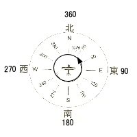 |
fig-5.1, such as "take-off direction"and"direction of the destination, " decides. Next, determine the speed of the destination you plan to fly, Determine the arrival time. After that, head for your destination with increasing altitude unobstructed aircraft rely on a compass. (This "dead reckoning navigation" is called.) "return path", the "forward path" Reverse (180 �� inverted orientation) to flight. However, in practice the effects of wind (crosswind, tailwind, headwind) and compass error (affected by the surrounding metal.), such as faulty. Therefore, it is a substantial short-range "pilotage navigation" useless should not be used. Can not see the runway and landing even arrived at the destination. So please remember as the navigation is always a backup can only be used in applications. Emergency, it should be understood that need. |
| fig-5.1 | |
[radio navigation flight]
Radio navigation is "flight instrument"and "ground support facility" means a system to follow will use the destination.
[inertial navigation system (INS)]
Principle, the gyros and accelerometers, "direction" and "Acceleration" is detected, you will see in the distance traveled by integrating the computer.
First, "current position" if you enter, the influence of bad weather or interference, "position" and "speed" you can always figure to calculate.
However, there is the disadvantage of increased accumulation of errors when you move a long distance.
Navigation now has "flight management system (FMS) " using the "inertial navigation system (INS) " and "navigation aid system " has to fly together.
[Global Positioning System (GPS)]
"GPS" global navigation satellite systems is a satellite-based precision.
Choose four or more satellites orbiting the earth, where can be learn to receive signals in three dimensions.
Aircraft can fly through the use of GPS in a single Navaids from takeoff to landing.
[ Navigation aid system]
The navigation area is "wide-area navigation"and "local area navigation"There are two ways of approaching.
5.2.Navigation Aid System
[Wide Area navigation]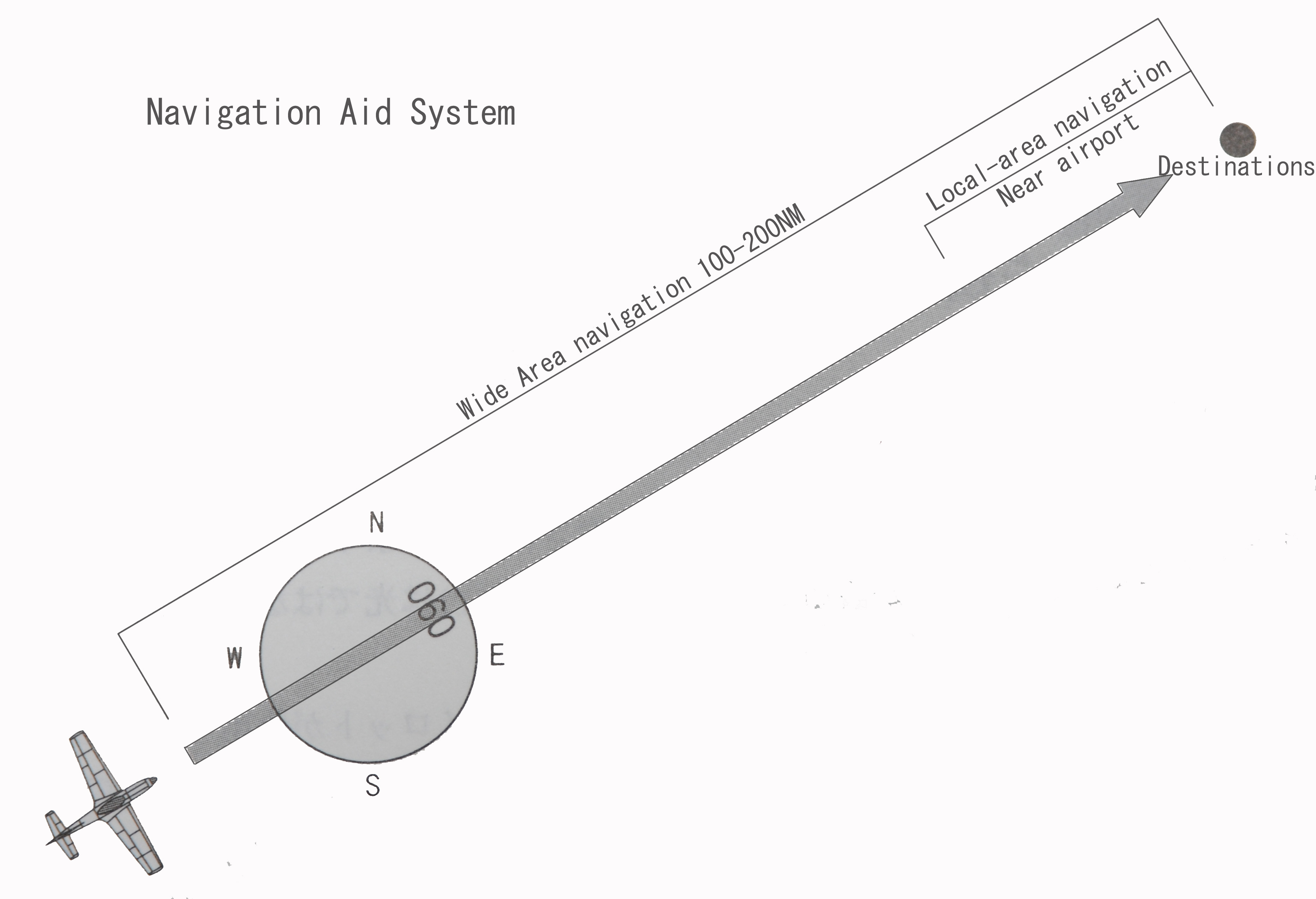 |
As its name suggests wide (far) is to cover an area navigation system. To the extent 100NM ~ 200NM (185Km ~ 370Km around) to cover the distance. This navigation is how to proceed to the two destinations.
|
| fig-5.2 |
[Local-area navigation]
"Local area" near the airport and the sight distance (horizontal line distance) is called a range of precision instruments can be induced within.
"Local Area Navigation"There are three types of tracking.
- VHF Omni�|directional radio Range beacon(VOR) tracking
- Instrument Landing System(ILS) tracking
- Visual Approach Slope Indicator System(VASIS)orPrecision Approach Path Indicator(�o�`�o�h) tracking
5.3.Description of wide-area navigation
[Non-Directional radio Beacon]
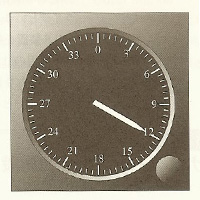 |
The most popular long-distance navigation instruments, airplane "ADF gauge" Non-Directionalredio�@Beacon(NDB) " fly to your destination using. |
| fig-5.3.1 ADF gauge |
|
Aotomatic Direction Finder (ADF) |
NDB 360 �� displayed in which direction they come from a radio. Pre-set to the desired frequency of the NDB, after takeoff, ADF will continue to guide the heading in the direction indicated by the gauge. |
| Non-Directionalredio�@Beacon (NDB) |
200 ~ 400KHz frequency of use. VHF Omni-directional radio beacon (VOR) accuracy compared to the low effective range 100 ~ 200NM and can cover long distances. Reach the destination (transit), the gauge pointer 180 �� so you can see that the inverted passes near the NDB beacon. However, the country has reduced the NDB beacon, VHF Omni-directional radio beacon that is now used in local area navigation (VOR) radio navigation and to relay the mainstream. |
[Distance Measuring Equipment and VHF Omni-directional Radio beacon]
|
Especially near the airport VOR DME stations are established at the station. It will be near the airport VOR navigation aid to tell the exact distance to the station.
|
||||||||||||
|
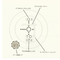
fig-5.3.2 VOR gauge (Omni Bearing Indicator OBI: Omni) |
| VHF Omuni-Directional redio Renge (VOR) |
VOR navaid which is currently the most widely used. 108 ~ 118Mz frequency band used. Valid range is expected to use (the Horizon) distance. |
| distance measuring equipment (DME) |
This device measures the distance between stations and aircraft. "The ground side transponder " and "the aircraft interrogator " operates in the pair. The aircraft is calculated by measuring the distance to the time difference between the two waves. VOR is a restaurant and usually has to be asked directions and distances. Also arrival at the destination point of DME distance display is "0" (zero) will not. This is because DME flight altitude of the aircraft are displayed with the station altitude difference. The distance will be increased to take away. |
5.4.Description of Local Area navigation
 |
As fig-5.4 causes the direction of the runway landing guidance using radio waves transmitted from the ground support facility near the airport approaches. Inductive content, "the direction of final approach"and "glideslope altitude, " the induction. |
| fig-5.4 Local Area navigation |
| VHF Omuni-Directional redio Renge (VOR) |
VOR is the final destination. (How to help is common and wide-area navigation.) |
| distance measuring equipment (DME) |
The distance to the airport. Consider the final approach descent from altitude to the reception. (DME if you do not have is the map of dead reckoning approach) (How to help is common and wide-area navigation.) |
| Instrument Landing System (ILS) |
Final approach to the induction of us. Final approach the aircraft entered a "Directional Wave" to send a unit to direct the course is to approach the runway. The device is organized as follows.
|
| Precision Approach Path Indicator �i�o�`�o�h�j |
If there is no ILS (or, ILS combination) is attached to the side of the runway guidance indicator attempts to rely on descent landing this indicator. The indicator device to indicate the angle of approach, you can see visually the height of the glidepath. fig-5.4 sequence indicator lights next four columns like the "two red lights"and "two white lights" to descend on the glideslope at induction. 4 red lights are too low, four white lights are too high. The inner marker(Sometimes middle marker), and landing again(go-around), if all red or all white. |
| *1"approach marker" type | |
|
Outer Marker beacon (Blue) |
Assigned altitude (just before the final approach altitude) is called the starting point in the glideslope. "ILS Induction" is the start of the final approach. |
|
Middle Marker beacon (Orange) |
This marker is located +200 feet from the landing point of decision. The airport is about automatic landing system, the category (CAT) *2has been determined by. Weather conditions (if the runway is not visible) is stopped by the landing or go-around. |
|
Inner Marker beacon (White) |
Landing decision point, beyond this point can not go-around. At any cost "landing"must be. |
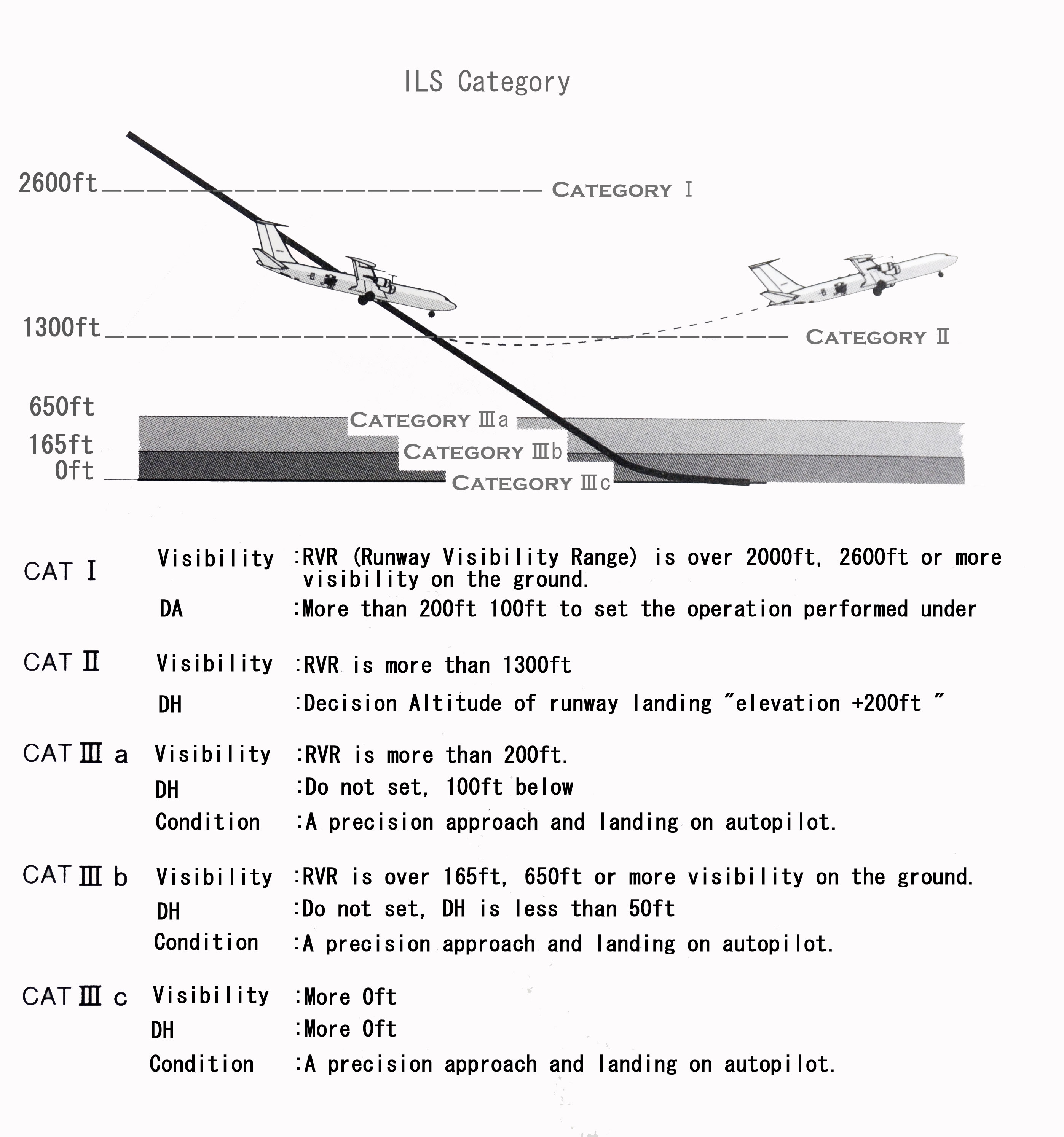
| *2 Category (CAT) Description | |
|
More and more airports are equipped with automatic landing system for the purpose of ensuring that you can safely land on bad weather. International Civil Aviation Organization (ICAO) in "all-weather landing system, " in five categories in order to promote the development of progressively (fig-5.4.2) is set. | |
 |
|
| fig-5.4.2 | |